After a long break (nearly 10 years!), it seemed like a good time to dust off this blog and post some updates to recent projects I have been working on. The blog has a new name, Hand-Rolled Noise (it used to be called Build Music Things), and an updated website.
This weekend I went to BEAM Day, a day of workshops for creating music and sound art machines. This day is part of this year’s events for the BEAM 2012 festival taking place 22-24 June at Brunel University. I can’t make the festival this year, so the BEAM day was a good chance to meet some people creating and experimenting with electronic music, sound art and performance controllers.
Alex Allmont created a collaborative workshop to build an electro-mechanical noise machine, the Polytherelegomuino. People were invited to build mechanisms out of LEGO that would in turn operate the controls of electronic synths. Each participant had a LEGO board to create a mechanism on with a turning shaft providing power, all driven from a central motor. The result was like a robotic synth knob-twiddling noise factory!
One of the Polytherelegomuino machines at BEAM Day 2012. I built the board to the right with the ‘hut’ on it, which housed a worm drive mechanism for slowly turning a frequency knob connected to the Arduino based synth.
Here’s a video of the final machine taken by Alex – WARNING: watch your speaker level, this is NOISY!
The synths used in the Polytherelegomuino are based on the Arduino synths of Mike Blow’s optical theremin instruments, the Theremuino and Energy Ball Theremuino which Mike was demonstrating on the day.
Mike Blow’s Theremuino at BEAM Day 2012.
Mike Blow’s Energy Ball Theremuino at BEAM Day 2012.
Codasign ran a workshop for controlling OSC compatible audio software, such as Max/MSP, with movement gestures via a Kinect. The Kinect to OSC interface they were using is built in Processing using OpenNI libraries, which allows a person’s movements to be tracked and mapped to OSC parameters. In the workshop they showed how a synth in Max/MSP could have parameters like pitch, number of harmonics and filter cutoff controlled by hand movements and standing position, all tracked through the Kinect.
Other workshops included Bruno Zamborlin’s mobile phone (accelerometer) based gesture recognition for controlling sound and Noisy Toys circuit bending workshop.
Like the Meeblip synth, the supported tool for Rockit development is AVR Studio which can only be used with Windows. It’s possible to build the Rockit code from the Mac OS X command line using the avr-gcc compiler and a new Makefile. The avr-gcc compiler is available for installation on Mac OS X through MacPorts. You’ll also need to install avrdude which is also available from MacPorts.
I’ve adapted this Makefile to build the Rockit code. This Makefile may also work with Linux, although I’ve not tried it. Simply place it in the directory with the Rockit source (make sure it’s named Makefile, not Makefile.txt) and type:
make
to build the source, then:
make hex
to create the Rockit.hex file for downloading. I’ve set up the Makefile to support the Sparkfun Pocket AVR programmer using avrdude so typing:
make install
will also upload the generated Rockit.hex file to the Rockit. If you’re using a different programmer, you’ll need to edit the writeflash target in the Makefile (line 199).
Alternatively, the avrdude command to upload the firmware is for the Sparkfun Pocket AVR programmer is:
avrdude -c usbtiny -p m644p -U flash:w:Rockit.hex
The avrdude options above can be modified to use your programmer.
The Rockit kit doesn’t ship with an AVR programming header, so you’ll need to solder your own header on the board. Here’s the correct way to connect the Sparkfun Pocket AVR programmer to the AVR header on the Rockit board:
Hackme Rockit with Sparkfun Pocket AVR programmer connected to the AVR programmer header. Note the orientation of the connector, with the wires facing toward the top of the board.
The header must be put on the top of the board so that the header pinout lines up with the AVR programmer connector. With a standard header on the board, this looks like it will make it fairly tight against the case, although I’ve yet to try assembling a Rockit case.
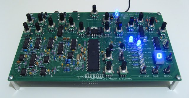
After a few sessions of building, the Rockit is finished and working!
The Rockit has 2 digital oscillators, a 2-pole analog filter with low-pass, band-pass and high-pass modes, and 2 LFOs that can be routed to different control inputs of the oscillators and filter. From first impressions of playing the Rockit, the analog filter sounds nice. The band-pass mode of the filter is especially good, and offers something different from standard low-pass filtering, which can give the Rockit a nice ‘vocal’ sound when played in this mode.
Here’s how you can build the Meeblip firmware on Mac OS X. For Windows, AVR Studio can be used to build the firmware. For Mac OS, the command line tool avra can be used, and presumably this will also work on Linux, although I’ve not tried this. Using avra to build the firmware was discussed on the MeeBlip forum, but I’ve summarised the steps below. This also includes the step to download the firmware to the MeeBlip microcontroller using the Sparkfun Pocket AVR programmer and avrdude. Full instructions for downloading the firmware can be found on the MeeBlip firmware page.
1. Download and build avra for Mac OS X and add it to your path
2. Install avrdude (one easy way is using Macports)
3. Locate the library file m32def.inc in avra (in avra-<version>/includes/) and copy it to your meeblip source directory containing meeblip.asm
4. Run the c pre-processor on m32def.inc to remove #define etc:
cpp -P m32def.inc > temp
mv temp m32def.inc
5. Remove the long comment in m32def.inc on line 465 as it is not compatible with avra.
6. Remove all comments (at the end of lines starting with a semi-colon) from meeblip.asm starting with a \ following the comment semi-colon and zero or more spaces as they are also not compatible with avra (these will be removed from future versions of the source). For example, remove comments from the end of the lines that have any of the following semi-colon backslash combinations below:
;\
; \
; \
; \
7. Assemble the meeblip source with:
avra meeblip.asm
8. Download the assembled hex using avrdude:
avrdude -c usbtiny -p m32 -U flash:w:meeblip.hex
If you’re using a different programmer, you may need to replace the avrdude -c option with the one for your programmer. Here’s a picture of how the Sparkfun Pocket AVR Programmer should appear connected to the MeeBlip:
Meeblip 1.31SE board with a Sparkfun Pocket AVR Programmer connected. Note the orientation of the connector, with the wires facing away from the audio and MIDI ports.
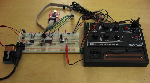
Gakken SX-150 synth, with MIDI interface circuit. A Sparkfun AVR programmer was used to program the attiny2313 microcontroller used in the circuit.
The Gakken SX-150 synth has a stylus which is touched on a continuous strip to control the pitch of the sound. It’s hard to play tuned notes using the stylus and so a MIDI interface for the SX-150 is a good mod to make the synth more usable. For this reason, several MIDI interface designs have been developed, including designs by RJ, Stray Technologies, Narbotic Instruments and Mrbook. All of these interfaces convert MIDI to a voltage (MIDI to CV interface) which is connected to the stylus.
The Narbotic and Mrbook design are both Arduino based, the others microcontroller based standalone circuits. I’ve had a go at making RJ’s design, prototyping it on a breadboard. The circuit works well, although as RJ points out, the accurate tuning range is about 2 octaves. Beyond that, the tuning needs tweaking to the higher octaves using the pot included in the circuit.
The circuit uses all the components described by RJ, except I swapped the TLP552 optocoupler for a 6N137. I used avrdude to program the attiny2313 microcontroller using a Sparkfun AVR programmer.
One gotcha that’s worth pointing out in getting this circuit to work is that the attiny2313 ships programmed to use the internal clock oscillator at 1MHz, but the circuit is designed to work at 20MHz using the connected crystal. The serial interface to the MIDI input is set up in the code to work at 20MHz, and will not work at 1Mhz. This is because, roughly speaking, the UART in the attiny2313 cannot be set to run quickly enough to accurately receive MIDI at 31.25kHz baud for a system clock of 1MHz in asynchronous receiver mode. The clock can be set to use the external 20MHz crystal by programming the ‘configuration fuses’ using avrdude. The oscillator configuration is set in the lower fuse bits. These can be read using avrdude as follows (this is for a Sparkfun programmer, option -c may need to be changed for other programmers):
avrdude -c usbtiny -p attiny2313 -U lfuse:r:-:h
Avrdude shows the default lower fuse configuration as 0x64. To use the external 20MHz crystal, the following avrdude command can be used:
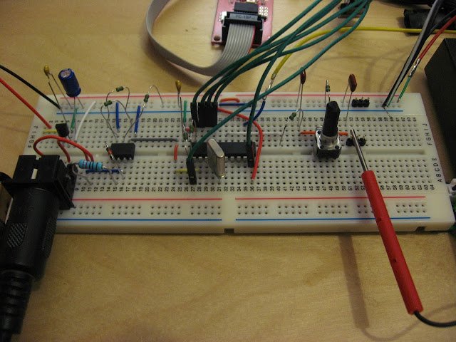
Update: I prototyped the MIDI interface onto a stripboard to have a permanent version of the circuit, here it is:
The prototype stripboard. A programming header (top centre of board) is included for programming the attiny2313 microcontroller with the Sparkfun AVR programmer.
Update 10/22: RJ’s original project page doesn’t appear to be online any longer so I’ve made a copy of RJ’s firmware available for download here.
The Rockit kit arrived last week from HackMe Electronics. A few people have already built working kits, I’m looking forward to building and powering it up. There’s a fair bit of soldering in this kit, so those of us building a kit have our work cut out…
Last weekend was the dorkbot interactive musical installation at the BV Open Studios Weekend held in the Bristol Hackspace and the kitchen at BV Studios.
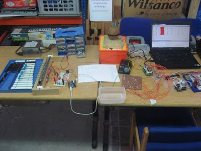
The Theremin Style Music Controller was set up in the kitchen along with two installations made by other dorkbot members: Richard’s biscuit-tin rhythm copying drums and John’s Tilty music box. Other installations included the Dorkbot Pisano wheels and Aaron’s Monome style ball-bearing controller, which triggered Anton’s electro-mechanical glockenspiel, a coconut and John’s octophone and LED level meters.
Thanks to all the people who came and had fun playing with the installation!
Monome style ball-bearing controller and connected instruments.
I’ve built a music controller that senses hand movements, in a similar way to a Theremin, for an interactive musical installation dorkbot bristol is exhibiting at the BV Open Studios 2011 this October. I’m hoping that people will be able to have some fun playing with the sounds of some music sequences being synthesized on a Mac by moving their hands in front of it. It has two sensors that measure how far your hands are above the box so you can move your hands up and down to control different aspects of the synthesized sounds. There are also four touch sensors that change the sounds being played when you rest a finger on them.
The aim is that the player should be able to explore the sound with their hand movements, the hand movements do not create the music itself. In this way, it should not require any special musical skill so anyone can have a go and make nice sounds, unlike a musical instrument like the Theremin which requires skill to play a tune.
The front panel. There are two IR distance sensors for the left and right hands and four touch sensors.
I wanted the hardware build to be as quick and simple as possible so the sensors are mounted in a cardboard box. The unit plugs into a Mac running Reaktor and controls the music being produced.
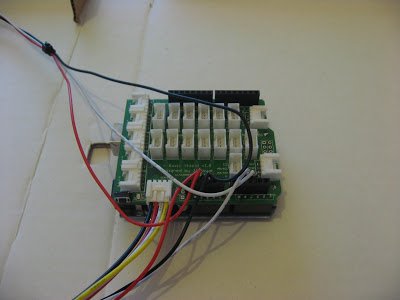
Inside the box.
The sensors are connected to an Arduino Uno, which has some code to send the sensor data as serial data over USB to the Mac. On the Mac, the control and routing of the sensor data is handled by some code developed in Processing to send the sensor data as MIDI and OSC to Reaktor.
The electronics components used in this project are:
Arduino Uno
Seeed Twig I2C Touch Sensor Controller and 4 Sensors
This website uses cookies to improve your experience while you navigate through the website. Out of these, the cookies that are categorized as necessary are stored on your browser as they are essential for the working of basic functionalities of the website. We also use third-party cookies that help us analyze and understand how you use this website. These cookies will be stored in your browser only with your consent. You also have the option to opt-out of these cookies. But opting out of some of these cookies may affect your browsing experience.
Necessary cookies are absolutely essential for the website to function properly. These cookies ensure basic functionalities and security features of the website, anonymously.
Cookie
Duration
Description
cookielawinfo-checbox-analytics
11 months
This cookie is set by GDPR Cookie Consent plugin. The cookie is used to store the user consent for the cookies in the category "Analytics".
cookielawinfo-checbox-functional
11 months
The cookie is set by GDPR cookie consent to record the user consent for the cookies in the category "Functional".
cookielawinfo-checbox-others
11 months
This cookie is set by GDPR Cookie Consent plugin. The cookie is used to store the user consent for the cookies in the category "Other.
cookielawinfo-checkbox-advertisement
1 year
The cookie is set by GDPR cookie consent to record the user consent for the cookies in the category "Advertisement".
cookielawinfo-checkbox-necessary
11 months
This cookie is set by GDPR Cookie Consent plugin. The cookies is used to store the user consent for the cookies in the category "Necessary".
cookielawinfo-checkbox-performance
11 months
This cookie is set by GDPR Cookie Consent plugin. The cookie is used to store the user consent for the cookies in the category "Performance".
viewed_cookie_policy
11 months
The cookie is set by the GDPR Cookie Consent plugin and is used to store whether or not user has consented to the use of cookies. It does not store any personal data.
Functional cookies help to perform certain functionalities like sharing the content of the website on social media platforms, collect feedbacks, and other third-party features.
Performance cookies are used to understand and analyze the key performance indexes of the website which helps in delivering a better user experience for the visitors.
Cookie
Duration
Description
YSC
session
This cookies is set by Youtube and is used to track the views of embedded videos.
Analytical cookies are used to understand how visitors interact with the website. These cookies help provide information on metrics the number of visitors, bounce rate, traffic source, etc.
Cookie
Duration
Description
_ga
2 years
This cookie is installed by Google Analytics. The cookie is used to calculate visitor, session, campaign data and keep track of site usage for the site's analytics report. The cookies store information anonymously and assign a randomly generated number to identify unique visitors.
_gid
1 day
This cookie is installed by Google Analytics. The cookie is used to store information of how visitors use a website and helps in creating an analytics report of how the website is doing. The data collected including the number visitors, the source where they have come from, and the pages visted in an anonymous form.
Advertisement cookies are used to provide visitors with relevant ads and marketing campaigns. These cookies track visitors across websites and collect information to provide customized ads.
Cookie
Duration
Description
IDE
1 year 24 days
Used by Google DoubleClick and stores information about how the user uses the website and any other advertisement before visiting the website. This is used to present users with ads that are relevant to them according to the user profile.
test_cookie
15 minutes
This cookie is set by doubleclick.net. The purpose of the cookie is to determine if the user's browser supports cookies.
VISITOR_INFO1_LIVE
5 months 27 days
This cookie is set by Youtube. Used to track the information of the embedded YouTube videos on a website.